Homework 2
Logistics
- The Guidelines provide important information about coding standards, expectations, and logistical considerations for this assignment.
- I recommend reading the guidelines both before starting the assignment and prior to your final submission:
- When a launch file is listed as
filename.launch.{py,xml}implement both an XML and python version. - All data files that are installed should be installed to the appropriate sub-directory of the package's share directory
(e.g.,
config/myfile.yamlshould be installed to$(find-pkg-share mypackage)/config/myfile.yaml) - For this assignment, do not read from
yamlfiles directly in your nodes.- Instead the appropriate values should be loaded into the node as parameters at launch time
- It is impermissible to
import yamlin your python code, for example.
- All python launch files should be written in a declarative style.
Overview
We will simulate a robot in ROS and integrate it into various standard ROS systems (e.g., tf, joint_states, etc.).
The robot will be used to catch a brick that is dropped from the sky.
The repository is called homework2 and there will be two packages within the repository
brickbot_interfaces- custom interfaces that are created for this projectbrickbotanament_pythonpackage containing everything else
Hints
Here are some general hints for this assignment:
- Familiarize yourself with the overall problem by reading the homework description.
- Work on the
urdf.xacrofile to build up the robot and the launchfile to visualize the robot simultaneously- It is especially useful to be able to view and manipulate the robot when debugging
.urdf.xacrofiles and the launchfile makes this process much simpler.
- It is especially useful to be able to view and manipulate the robot when debugging
- Slowly introduce node functionality over time.
- Write launchfiles early in the process. Use these launchfiles to make testing nodes easier.
Frames
The following coordinate frames will be used:
world. This is the fixed frame, representing the location of entities in the world- All other frames are descendants of
world
- All other frames are descendants of
brick. This frame is the location at the center of the brick's bottom surfacebase_link. This frame is the base location of the robot- The
base_linkhas other child frames, as defined by the robot'surdffile
- The
odomframe: the robot's position based on its odometry is relative to theodomframe.- The position of the
odomframe relative to the world represents where the robot started
- The position of the
The Robot
Overview
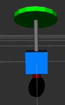
- The robot is modeled as a unicycle robot that "self balances" on a caster. It consists of
- A
base_linkthat is the main location of the robot and is represented by a cube. - A
platformis a flat square- The base of the
platformshould be parallel to the ground in the zero position, but should be able to rotate so that the brick can be dumped. - The
platformshould be a fixed vertical distance above thebase_link, so that it may rotate fully without colliding with the base link. - A fixed cylindrical link called
hingeshould connect thebase_linkto theplatform - The platform rotates about it's
+yaxis via a joint calledalpha
- The base of the
- A
stemis a cylindrical link that turns about the vertical z-axis and is below thebase_link, connected by a joint namedtheta - A
wheelis connected to thestemby a joint namedphiand can roll as the robot moves - Each link should be a different color.
- A
- The robot has a maximum translational speed but infinite rotational speed, making it effectively omni-directional
- To move in a given direction, the
stempoints in that direction and then the robot translates (while the wheel rolls).
- To move in a given direction, the
- The
.urdf.xacrofile for the robot should be inurdf/robot.urdf.xacro - The visual and collision components can be the same. Inertia can be omitted for this homework.
- Use
xacrofeatures to avoid redundancy when defining the visual and collision components. - Any
xacromacros used should be defined inurdf/macros.xacroand included in the mainxacrofile.
- Use
- The
xacrofile should take in an argument for aconfigfile, which defaults torobot.yaml
The image below is illustrative: however, the platform is a square rather than a cylinder.
Configuration
- A configuration file called
config/robot.yamlshould have the following parameters- The
platform_heightof the robot'splatformabove the ground - The
platform_lengthis the length of the platform's side - The
wheel_radiusof the robot's wheel - The
max_velocity, maximum translational velocity of the robot - The default values of these configuration items can be chosen by you.
- The
- The
.urdf.xacrofiles should useconfig/robot.yamlto set its dimensions appropriately- Other dimensions that are not specified should be specified as constants within the
urdf.xacrofile.
- Other dimensions that are not specified should be specified as constants within the
- Changing
config/robot.yamlshould be the only change needed to change these dimensions of the robot. - Also create a configuration file called
config/big_robot.yamlwith different parameter values.
Visualizing the Robot
- Write a launchfile called
launch/show_robot.launch.{py,xml}that displays the robot (as defined byrobot.urdf.xacro) inrviz- The launchfile argument
use_jspcontrols the behavior of thejoint_state_publisher- If
use_jspisguithen thejoint_state_publisher_guiis used to publish joint states (the default) - If
use_jspisjspthen thejoint_state_publisheris used to publish joint states - If
use_jspisnonethen no nodes that publishjoint_statesare started by the launchfile - Document the arguments so that the documentation shows up when using
ros2 launch -s
- If
- The launchfile argument
rviz_configcontains the name of thervizconfiguration file relative to the project's share directory. - The launchfile argument
robot_configcontains the name of the robot configuration file relative to theconfigdirectory. It defaults torobot.yaml - The launchfile argument
use_rvizdetermines whetherrvizis started
- The launchfile argument
- The launchfile starts any other nodes that may be necessary to display the URDF in
rviz
Physics
- A python module called
physics.pyshould contain ROS-independent code to keep track of the physics of the environment.- It must not
importany ROS python modules
- It must not
It should provide classes with the following definition.
class Brick:
    '''Keep track of the physics of the Brick.'''

    def __init__(self, location, gravity, side_length, dt):
        '''
        Initialize the brick.

        Args:
        location - The (x,y,z) location of the brick. It is axis aligned.
        gravity - the acceleration due to gravity in m/s^2
        side_length - the side_length of the platform
        dt - timestep in seconds of the physics simulation
        '''
        pass

    @property
    def position(self):
        '''
        Get the brick's position.

        Return:
            (x,y,z) location of the brick
        '''
        pass

    @position.setter
    def position(self, pos):
        '''
        Set the brick's position.

        Args:
           pos - the (x,y,z) location of the brick
        '''
        pass

    def drop_gravity(self):
        '''
        Update the brick's location by having it fall in gravity for one timestep.
        '''
        pass

    def slide_ramp(self, radians):
        '''
        Update the brick's location as it slides on a frictionless ramp for one timestep.

        Args:
           radians - the angle of the ramp
        '''

class Robot:
    def __init__(self, config, dt):
        '''
        Initialize the Robot.

        Args:
        config - The (x,y,alpha) position of the robot + tilt of the platform.
        dt - timestep in seconds of the physics simulation

        '''
        pass

    @property
    def configuration(self):
        '''
        Get the robot's configuration.

        Return:
            (x,y,alpha) configuration of the robot
        '''
        pass


    def drive(self, velocity):
        '''
        Update the robot's position after driving for one timestep.

        Args:
           velocity - (dx/dt, dy/dt) relative to the robot's body
        '''
        pass

    def tilt(self, alpha):
        '''
        Tilt the platform to the specified angle

        Args:
           alpha - the angle of the platform relative to the horizontal.
        '''
        pass
Simulation Node
Overview
The simulation node acts as fake hardware for this assignment. It manages and has full knowledge of the brick and the robot.
- Robot and brick state are updated by the
physicsmodule - The
simulationnode is implemented insimulation.py - Parameters for the
simulationnode are:width, lengthThe dimensions of the arenax0, y0- The initial position of the robotgravity- Gravitational accelerationtimestep- Simulation timestep
- Parameters should be stored in
config/simulation.yamland loaded via launchfile - Many of the parameters in
config/robot.yamlare also needed and should be loaded.
Simulation Loop
- The simulation is driven by a single timer with a period of
timestep - Each tick of the timer corresponds to a single simulation step
- All publishing and broadcasting should be done from the timer callback
The Arena
- Drawing walls on the arena boundaries using markers:
- These should be published as a
visualization_msgs/msg/MarkerArrayon thevisualization_marker_arraytopic in thearenamarker namespace
- These should be published as a
- Broadcasting the
brickframe at the location of the brick, and a marker to show its location inrviz- The
brickmarker is published on thevisualization_markertopic in thearenamarker namespace - The
brickshould of theCUBEtype.
- The
- Offer a
placeservice (of custom typebrickbot_interfaces/srv/Place) that moves the brick to a specified position- The service has a request type of
geometry_msgs/msg/Pointwith a member calledpositionand an empty response - Only the
x,y,zcoordinates are moved, the brick maintains a fixed orientation relative to theworld
- The service has a request type of
- Broadcast a static transform from
worldtoodombased on the initial position of the robot.
Brick Dynamics
- Offer a service called
drop(of typestd_srvs/srv/Empty) that causes the brick to fall in gravity according to the specified rules:- After the service responds, the brick starts falling in gravity (using the specified
gravityacceleration). - If the brick hits the platform or the ground it stops falling.
- If the brick hits the platform it should move with the platform
- Your code can assume that the platform is at 0 degrees when the brick is dropped and does not need to handle other cases.
- After the service responds, the brick starts falling in gravity (using the specified
- The brick slides on the platform based on
gravityand the platform angle, with zero friction- When the brick is completely off the platform it freezes and floats in space
- By construction the sides of the platform and of the brick are always aligned.
- Angle of the brick's bottom relative to the ground should always match that of the platform
Robot Dynamics
- The simulation tracks the state of the robot according to a simple kinematic model.
- Velocity commands are received by subscribing to
cmd_vel(geometry_msgs/msg/Twist)- The robot state is updated in the simulation loop
- Only
xandylinear velocities are executed, others are ignored - Velocities above
max_velocityare ignored - The wheel immediately pivots to point in the direction of motion
- The wheel should rotate to simulate rolling without slipping
- The robot publishes a
sensor_msgs/msg/JointStatemessage on thejoint_statestopic - The robot simulation subscribes to
tiltof custom typebrickbot_interfaces/msg/Tilt, which has a single memberangle, of floating point type.- The platform's tilt angle should be updated on the next simulation step
Control Node
Overview
The control node is implemented in control.py and it is responsible for higher-level control and odometry
- The
controlnode should have any parameters it requires, as defined inconfig/robot.yaml - The
controlnode is driven by a timer that executes at 100Hz.- Everything published/broadcast from this node happens from the timer callback
- The
controlnode subscribes to agoal_posetopic of thegeometry_msgs/msg/PoseStampedmessage type.- Only
goal_posesrelative to the world frame are accepted - When the node receives this message it starts driving the robot toward the goal pose by publishing
cmd_velmessages - When the robot is not moving, the node publishes a
cmd_velof 0
- Only
- The
controlnode subscribes to thejoint_statestopic and computes wheel odometry- It should publish a
nav_msgs/msg/Odometrymessage (covariance can be ignored) on theodomtopic - It broadcasts a transform from
odomtobase_linkbased on the odometry calculation
- It should publish a
Launch
- Write a launchfile called
control.launch.xmlthat- Starts the
simulationnode - Starts the
controlnode - Includes
show_robot.launch.{py,xml}as appropriate to draw the robot inrviz- Python launchfiles can be included in xml launchfiles and vice versa, you can use any combination you would like here.
- You can now test the
goal_posecommand and should see the robot move to the goal location
- Starts the
- The
launchfilehas ause_rvizargument to decide whether to startrviz
Catcher Node
Overview
- The
catchernode is implemented incatcher.py- It can use any parameters it needs as specified in
config/robot.yaml - It can read the
gravityparameter fromconfig/simulation.yaml
- It can use any parameters it needs as specified in
- Write a node called
catcherthat causes the robot to catch a falling brick - The node knows the brick's location based on the
bricktf frame and monitors it. - When the node detects that the brick is falling it:
- Computes (based on
max_velocity) whether it can reach the brick in time to catch it- If the brick cannot be caught, the node publishes a Text marker that lasts for 3 seconds that says "Unreachable"
- The marker is published on the
visualization_markertopic in thecatchermarker namespace
- The marker is published on the
- If the brick can be caught, the robot drives under the brick and catches it.
- If the brick cannot be caught, the node publishes a Text marker that lasts for 3 seconds that says "Unreachable"
- Computes (based on
- When a brick is caught, the robot
tiltsthe brick until it is off the platform (and just floating in space!).
Launchfile
- Write a launchfile called
catcher.launch.xmlthat runs all the nodes necessary for the robot to catch a brick- The launchfile should include
control.launch.xmlas needed - The
rvizconfiguration should show the robot, the arena, and the brick - The launchfile has a
use_rvizargument to decide whether to launch rviz
- The launchfile should include
Testing
- Your code should pass all the standard tests that are run with
colcon test - Write at least one
pytestunit test for:physics.Robot.drivephysics.Brick.drop_gravityphysics.Brick.slide_ramp
- Write a test launchfile called
test_brick_launch.pythat verifies that thecontrolnode publishescmd_velcommands at 100 Hz - Write a test launchfile called
test_frames_launch.pythat- Places the brick directly above the platform
- Drops the brick
- Tilts
- Verifies that a brick, after sliding, stays in the correct location
- Your final result should not have any
rvizerrors or warnings once all nodes in a given launchfile have started running.
README
In the base directory of your repository (e.g. homework2) create a README.md using the following template (be sure to update the ${} with the answers.)
# ME450 Embedded Systems Homework 2
Author: ${Your Name}

${A brief overview of what the package does}

## Quickstart
1. Use `ros2 launch ${pkg} ${launchfile} ${options}` to start the arena and robot simulation
2. Use ${ros2 service call here} to place a brick
3. Use ${ros2 service call here} to drop a brick
4. Here is a video of the robot when the brick is within catching range
   ${embed video here, it must be playable on github. Upload the video as an issue and link to it}

5. Here is a screenshot of the robot when the brick cannot be caught

   ${embed image here, it must be viewable on github.}

6. Here is a screenshot when =big_robot.yaml= is loaded by the show_robot.launch.xml launchfile

   ${embed image here, it must be viewable on github.}