Homework: Mobile robot control, inverse kinematics, URDFs, and markers
Table of Contents
1 Submission Instructions
Just like all other assignments so far, this will be submitted via Classroom for GitHub. See Canvas for the secret link for creating your private repository.
The final deliverable for this assignment will be a single ROS package that contains all of the nodes, launch files, URDFs, etc. to complete the tasks below. The package will be pushed to your GitHub Classroom repository, and a URL similar to https://github.com/ME495-EmbeddedSystems/homework-1-f2018-YOUR-USERNAME should be submitted via Canvas before the due date.
2 Trajectory Following Control for a Differential Drive Robot
In this section, you will work with the turtlesim package, a simple package used
for teaching basic ROS concepts. Your goal is to create a ROS package containing
a node that controls the turtlesim to follow a reference trajectory.
Start this task by creatin a ROS package using catkin_create_pkg. As you
answer the rest of the questions be sure to keep your package.xml and
CMakeLists.txt files up-to-date with the packages you depend on. In this
package Initialize a Git repository that tracks all relevant files for your
package, and doesn't track any unnecessary files (likely you'll want to use a
.gitignore file). I especially don't want to see backup or autosave files
created by your text editor tracked by Git (e.g. no scriptname.py~ or
.#scriptname.py files).As you complete the rest of this section, try to
commit as you go. Once your local repo is initialized, you'll want to add the
private GitHub repo created by GitHub Classroom as a remote. Your command
will look something like
git remote add origin git@github.com:ME495-EmbeddedSystems/homework-1-f2018-USERNAME.git
The primary goal of this section is to Write a node that makes the turtle follow a reference trajectory given by
\begin{equation*} \hspace{-25pt}x_{d}(t) = 3 \sin{\left(\frac{4\pi t}{T}\right)}+5.54 \qquad y_{d}(t) = 3 \sin{\left(\frac{2\pi t}{T}\right)}+5.54 \qquad t \in [0,T]. \end{equation*}
This is a vertically-oriented "figure 8" centered at \((5.54,5.54)\) – this
offset is because the turtlesim uses the bottom left of the window as the
origin and the turtle is not allowed to go out of the first quadrant. The
turtle should complete one traversal of the reference in \(T\) seconds. Don't
worry if your figure 8 isn't oriented perfectly. Here are a few hints:
- You will want to call the
turtle1/teleport_absoluteservice to get the turtle located and oriented correctly for the reference trajectory at \(t=0\). - The turtle follows a standard kinematic-car model (sometimes called the
unicycle model or a differential drive). This means only two of the
values in the
cmd_veltopic are actually used when integrating the turtle's kinematics. - The turtle is what's called a "differentially flat" system. For our purposes, this means that given the reference above, we can analytically calculate the translational and rotational velocities to command the turtle with to exactly follow the reference.
- There are well-known algorithms for generating the rotational and translational velocity signals required to get this kinematic car model to perfectly follow the given reference trajectory. Feel free to use algorithms that you find in research papers, but be sure to cite your source.
Make your node accept a private parameter (not a command-line argument) that can be used to override the default value for \(T\) (the user can then specify at runtime how fast the turtle should go).
Use rosbag to record enough messages on the /turtle1/cmd_vel topic to have
the turtle complete one circuit of the reference. Note that the -l option to
rosbag can be used to control how many messages are recorded. You can then
use rosbag to play back your recorded messages to control the turtle without
ever starting up your node.
2.1 Turtlesim Deliverables
Your repository should have commits containing the node described above, a commit where you added a copy of your bag file, and a README. The README should contain a high-level description of your code and this repository in general. You should be sure to describe which Python script contains the node (with links), the ROS topics/services that this node provides/uses, and point out any critical lines of code. Since you've also provided a private parameter for the user to specify the trajectory's period, this should also be documented. You should also include complete instructions for running your node, including any nodes that your node depends on.
Use something like SimpleScreenRecorder to record a video of your turtle completing the figure 8 and add a link to this video in your README. The video should not be committed to your repo; rather, you should use an online service like YouTube or Vimeo to host your video, and then link to that service. Note that Markdown also supports raw HTML, so if you wanted to embed the video directly in the README that would be completely possible.
3 Analyzing a Two-Link Planar Robot
In this problem we will be working with a simple two-link planar robot, as shown in Figure 1. For this problem \(l_1 = l_2 = 1\), the configuration space of the mechanism is \(q = [\theta_1, \,\, \theta_2]\transpose\), \(B\) is the coordinate system at the base of the mechanism, and the \((x,y)\) in the upper right represents the coordinates of the black point on the end effector expressed in the \(B\) frame.
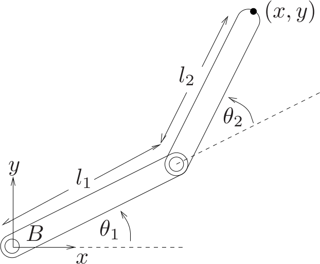
Figure 1: A simple schematic of a two-link planar robot. This version was borrowed from A Mathematical Introduction to Robotic Manipulation. See the book's wiki.
3.1 Generating a URDF
Write a URDF that represents the two-link system in Figure 1. You may want to
set the colors of the two links to be different so that it is easier to
distinguish between them in rviz. You may find the joint_state_publisher
with _use_gui:=true will help you in debugging your URDF. Don't worry about
joint limits, any properties related to dynamics (e.g. inertia), or
collisions. You should only need to define links, joints, and visual
properties. There are many different ways one could convert Figure 1 into a
URDF representation. Be sure that however you choose to construct the URDF,
you have the following properties:
- When \(\theta_1=\theta_2=0\) the entire robot should lie along the \(x\) axis of the tf frame at the base of your URDF tree. Note that in Figure 1 if \(\theta_1=\theta_2=0\) the longitudinal axis each link is aligned with the \(x\) axis of frame \(B\).
- Ensure you have a tf frame at the location of the black dot in Figure 1. Depending on how you build your URDF, this may require adding a fixed joint at the end of link 2.
3.2 Inverse Kinematics
In this section you will write a ROS node that will publish a
sensor_msgs/JointState message on the joint_states topic at
approximately \(50~\mathrm{Hz}\) to control the mechanism from the previous section.
Your goal is to have the black dot at the end effector follow a reference
trajectory given by
So the end effector should trace out a circle of diameter 1 that is symmetric across the \(x\) axis of frame \(B\), and shifted 1.25 units in the positive \(x\) direction from the origin of \(B\).
3.3 Animating a Trajectory
In this section you will create another ROS node that repeatedly uses either
tf.TransformListener.lookupTransform or tf2_ros.Buffer.lookup_transform
to find the transformation between the frame at the base of your mechanism
and the frame at the end effector of the mechanism. The first method will
return two Python tuples – the first containing the \((x,y,z)\) translation
between the frames, and the second containing a quaternion representation of
the rotation between the frames as \((x,y,z,w)\). The second method will
return a geometry_msgs.msg.TransformStamped containing the transform
information. Either way, you will use your knowledge of this transform to
publish a visualization_msgs/Marker that can be used in rviz to visualize
the path that the end effector has traversed. Since these Marker messages
are quite large, you will not want to publish on your marker topic any faster
than \(\approx20~\mathrm{Hz}\).
You can use whatever display type that you think best illustrates the path of the end-effector. Here are some tips that might help you get started:
- Don't forget to add timestamps and frame information to the
Headerfield of your Marker messages. Without timestamps or frame information,rvizcannot properly display the messages. - Note all numeric fields start out with a default value of zero. If you don't fill out things like size and color, your markers will not be visible.
- Pay attention to the
idfield of your message. If you are using a display type that only displays a marker at a single pose (e.g. a SPHERE, but not a LINE_STRIP or POINTS), then you'll need to make sure that every object you ADD has a differentid. - Since our reference trajectory is cyclic, make sure that the markers from
the last cycle are not overlapping with the markers from the current cycle.
Our cycle takes \(\approx\) 5 seconds, and the trajectory you animate should
contain less than 5 seconds worth of data at any given point in time. For
something like a SPHERE, this can be managed with the
lifetimefield, and for something like a LINE_STRIP or POINTS you simply manage how many points you publish. - You cannot use the "Show Trail" option from the Robot Model display in
rvizto animate the end-effector trajectory.
3.4 Two-Link Robot Deliverables
When this section is complete, you should have a single launch file that
starts both nodes from the previous two sections, loads the URDF from the
first section to the parameter server, and starts rviz with the -d
argument to load a nice .rviz configuration for viewing your animations. It
would probably be worth your time to add arguments to your launch file that
allows you to change how your program runs at runtime. Some examples of
things that would be useful for a user (including yourself) running the
package include modifiable frequencies for publishing relevant messages,
adjustable time periods of the circle that the end effector traces, control
over whether rviz is automatically started, and the ability to select
whether the joint angles should be set by your inverse kinematics control
code, or through the joint_state_publisher.
All relevant files from this section (2 Python scripts, a launch file, a
URDF, and an rviz configuration) should be in your ROS package, there
should be multiple commits that go along with completing this section, and
your README should be updated to include documentation for this section
(important files, relevant topics/services, running instructions,
descriptions of which Marker type you are using, etc.). Finally, you should
record another video showing your rviz animation of the robot completing
the reference circuit. Be sure I can see the Displays panel so that I can
verify the end-effector trajectory I'm seeing is from a Marker message.
Upload this video to an online service and include a link in your README.
